Posted on October 12, 2017
What is Power Injection?
At its lowest level power injection is nothing more than adding additional power to a string of lights at a point in which the voltage drop starts to affect the lights. There are a number of questions that always asked in reference to that.
- What if I have multiple power supplies?
- What if my pixels are different voltages?
- How do I know where to inject power?
- What is the common ground and why do I care about it?
We will cover all of these and more in this article.
Guiding principles and overview:
This articles is designed to be voltage agnostic and can be applied to either a 12v or 5v configuration as the principals are the same. The primary difference between them is voltage drop and the operating level of the pixel itself. There are also a number of variables that can affect power as such this is not designed to be a bible but provide the tools for you to successfully power your display. Here are the "general" rules for power injection.
12 volt pixels - Inject every 100 pixels
5 volt - Inject every 50 pixels
Now the question of why are these numbers used so often, it all comes down to voltage drop, for both the 5v and 12v at 50 and 100 pixels respectively you will see about a 15% loss in power which is within the operating level, over that, you may start seeing issues. Does this mean you should always inject power at these marks no but we will get in to that later.
Identifying potential power related issues:
If you turn on your lights and try to make them white but instead you get a mix of white, yellow and red … typically progressively as you move along a string of lights then you have a problem that may be helped by power injection
RGB lights are made up of 3 LEDs, red green and blue. Each of these LEDs have slightly different electrical characteristics which lead to different behavior as voltage drops. Specifically in order as voltage decreases Blue, then Green and finally the Red LEDs will stop working. What this means is if you have a set of lights turned on to be white and you have insufficient power the LEDs will progressively as you move along the string go from white, to yellow, to red and finally dim to black. To solve this you need to inject power to bring the voltage back up to an acceptable range.
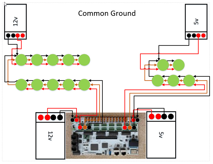
Power Injection and the "Common ground"
What is the common ground and why do we need it? It is nothing more than to ensure throughout your display you have a return line for data. Data, what does data have to do with the 12v or 5v ground (V-) wire? Like any circuit you need to have a return path for a closed loop and in our setups ground is the return path for data back to the controller. Without a common ground data will go out but it cannot complete the circuit your pixels will not function as expected. So again what is the common ground, it is ensuring the V- on any and all power supplies no matter what their voltage is are connected together.
Voltage Loss Reference Table
| % Loss |
12v Voltage Loss |
5v Voltage Loss |
| 0-20% |
0-2.4v |
0-1.0v |
| 21-30% |
2.41-3.6v |
1.1-1.5v |
| +30% |
+3.61v |
+1.51v |
Power Injection Scenarios:
DISCLAMER: In all the scenarios we will be using they are assuming a 20 foot lead line, 18 awg copper wire and 100% intensity on white unless otherwise noted from the controller and from injection power supplies. The pixels are assumed as follow 12v 60ma 5v 25ma. These scenarios will also always be powering the first pixel prior to any power injection points.
- Every wire is a resistor and will lead to voltage drop. It is small but it has an impact.
- Voltage drop is proportional to wire length … it gets bigger as the wire gets longer
- Resistance increases as the wire gets smaller but the material in the wire and the type of wire (stranded vs solid) also make a difference to the resistance per meter/foot.
- If you run 2 wires in parallel this effectively doubles the wire diameter and lowers the effective awg
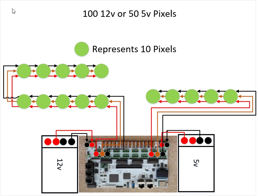
Scenario A – Running up to 100 12v or 50 5v pixels
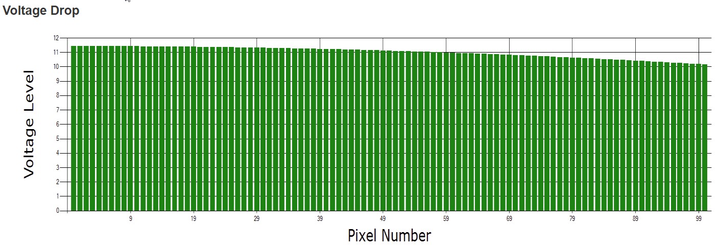
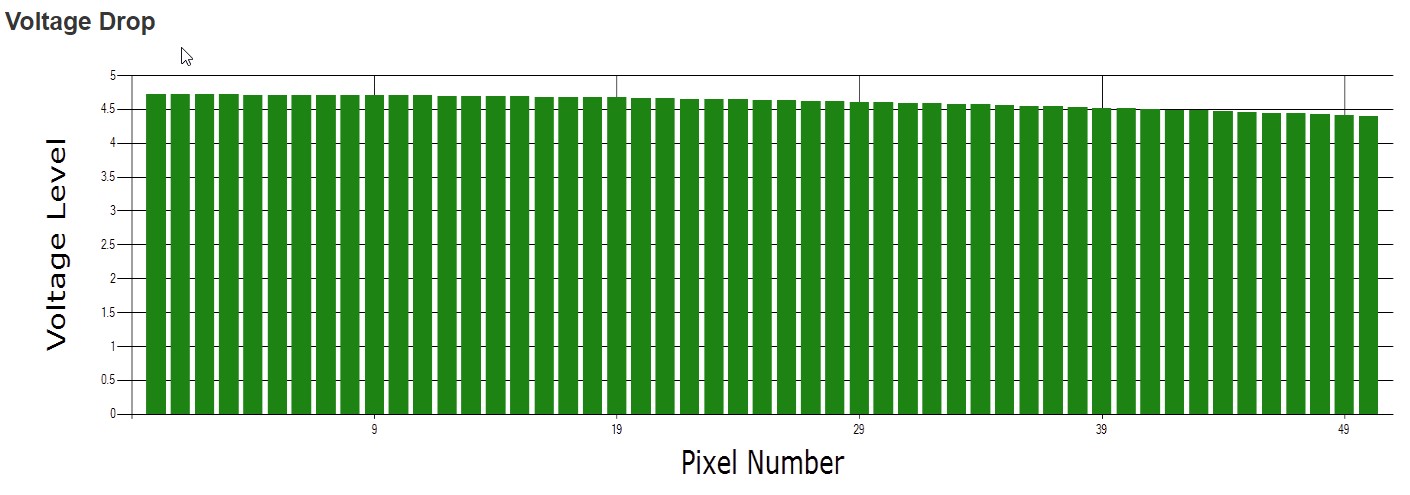
This is the simplest of all as no power injection is required as depicted in the follow image power draw graphs.
You’ll notice the power loss is under 20% or (2.4 volts for 12 and 1 volt for 5v) overall well within the range of operating the pixel on both the 5v and 12v.
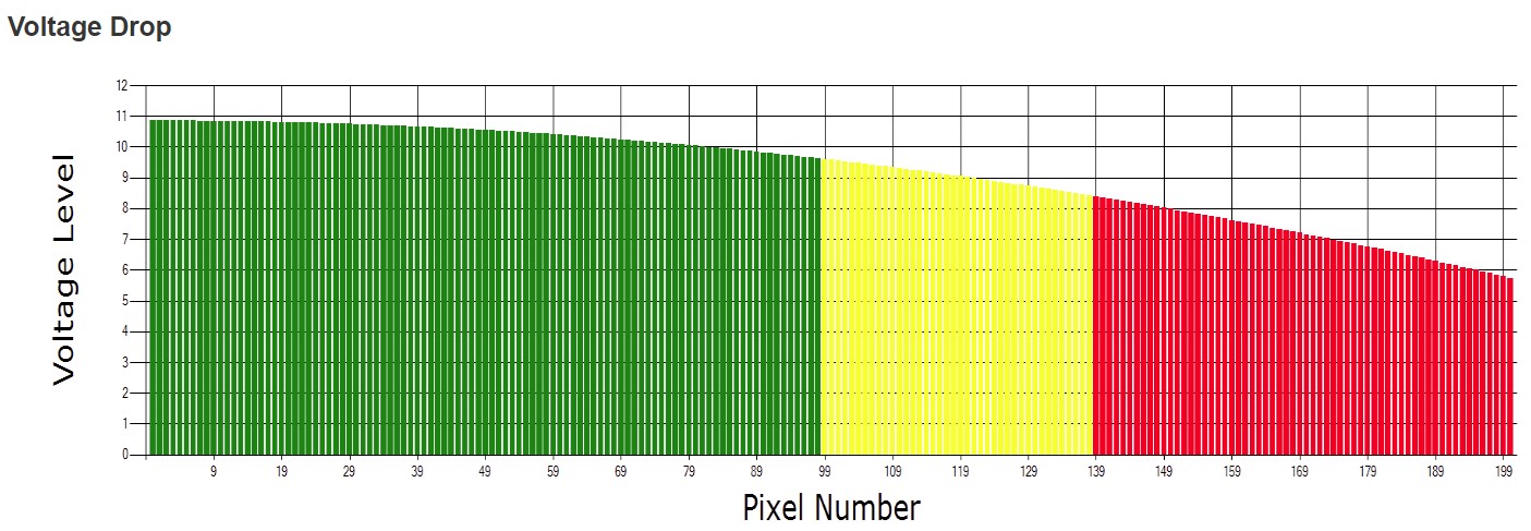
Scenario B –200 12v or 100 5v pixels same power supply
In this scenario we are going to focus on 12v pixels but the same concept applies to 5v pixels. As you can see in this power graph you cannot run 200 12v pixels reliably without power injection. You may be asking yourself why there is such a dramatic difference by only adding 100 more pixels. The simple answer is you doubled the amps being pulled through the 18 awg wire resulting in a higher power loss from the controller to the first pixel. In our 100 pixel example the loss at the first pixel was 6.4% and with the additional 100 pixels draw it was 12.8%. With that let’s inject some power and balance the load.
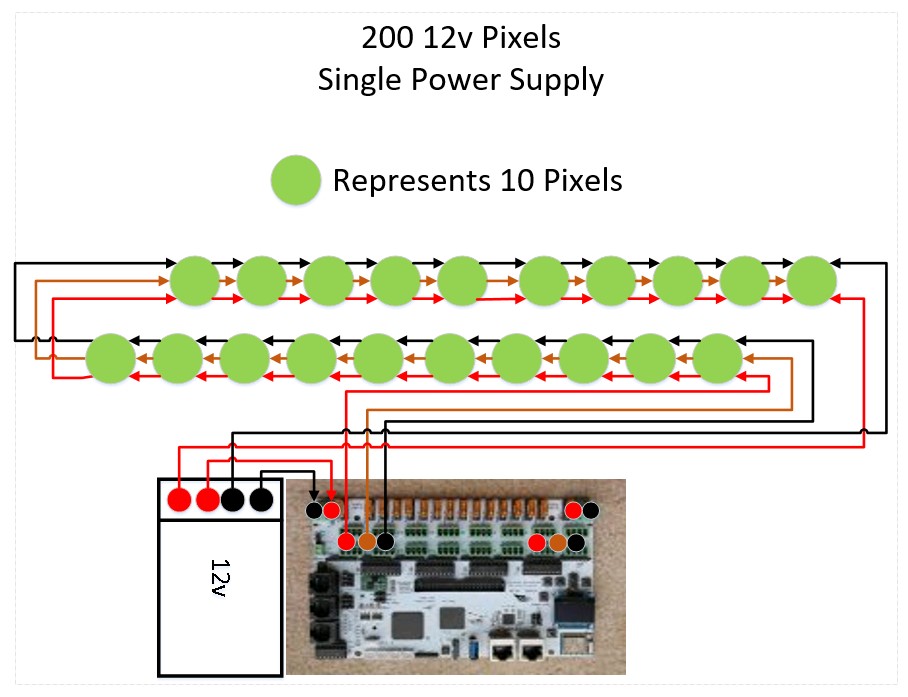
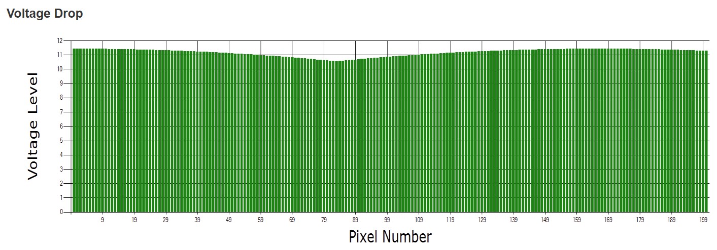
Option A – Inject power at the end from the same original power supply.
You will notice in this graph the load is balanced between pixel 1 and pixel 200 with a max power loss of about 15% under the 20% power loss point in which issues can start to arise. This option is most commonly used in mega tree and matrixes.
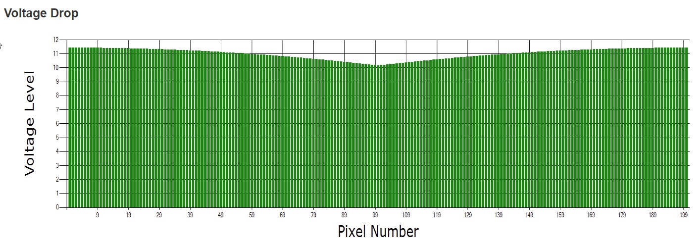
Option B – Inject power at the 2/3 point (pixel 166) from the same original power supply.
You will notice in this graph the load is balanced between pixel 1 and pixel 200 with a max power loss of about 9% well under the 20% power loss point. In this instance the power loss is 6% less than it was when we just injected power from the end. The reason being is we have evenly distributed the power in all directions between all the pixels. This option is most commonly used in house outlines, matrixes and other large props or between strings of props.
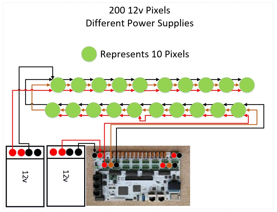
Scenario C –200 12v or 100 5v pixels different power supply
In this scenario we are going to focus on 12v pixels again but the same concept applies to 5v pixels. Unlike before when everything was coming from the same power supply we need to take into account other considerations, mainly that we need to make sure NOT to cross the V+ and then we re-inject power at the first pixel. We will also follow the standard guideline of injecting every 100 pixels as they are truly 2 separate strings that share data and ground but have different power sources.
Scenario D – Really long string of pixels
With our controllers being able to send data across a large number of pixels it is very inviting to do so but what does that actually look like. In our example we are going to assume 680 pixels. Now our controllers from a single power could never power that many pixels as such injection is going to be required. In order to determine the optimal number of injection we need to do some math. We know that in any 1 direction we can power 100 pixels. So to keep the math simple let’s call it 700 pixels. That gives us 7 sections of 100 pixels. We have the start of the string powering the first 100 pixels leaving me 6 sections and each injection wire can power 2 sections as the power flows in all direction meaning I will need 3 injection point assuming this is all being powered from the same power supply.
- Start of string 100 pixels
- Inject at pixel 200 covering 101 to 300
- Inject at pixel 400 covering 301 to 500
- Inject at pixel 600 covering 501 to 700
Here is the resulting graph in this configuration.
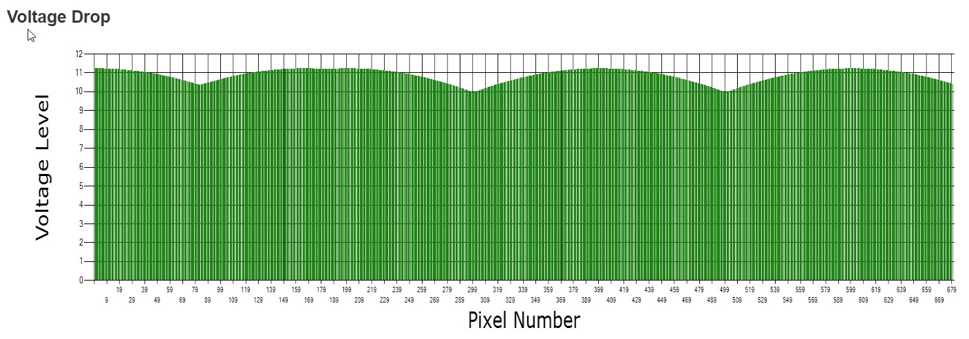
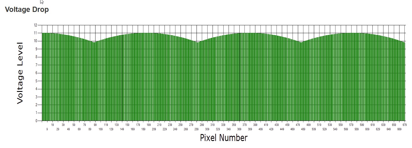
You’ll notice the power is not perfectly balanced but under the 20% loss threshold which is what you want to achieve. If you want to actually balance it you would simply take the difference between our base calculation of 700 and the actual count of 680 resulting in 20 pixels and spread it among the 7 sections resulting in the following.
- Start of string 97 pixels
- Inject at pixel 194 covering 98 to 291
- Inject at pixel 388 covering 292 to 485
- Inject at pixel 582 covering 486 to 680
Here is the resulting graph in this configuration.
More than likely in the real world you are not going to be injecting from the same power supply that is powering your board and you will use a separate power supply to inject with. The same principal applies here as it did in our previous example the only thing that changes is your math.
- Start of string 97 pixels
- Start of string pixel 98 from new power supply
- Inject at pixel 291 covering 194 to 388
- Inject at pixel 485 covering 389 to 680
To be continued based on feedback ….